G2 Manual Spike Driver
G2 Manual Spike Driver for the GS001 Turn and Lock™ Ground Spike.
Manual Driving Tool for the GS001 Turn and Lock™ Ground Spike.
Simply fits onto the GS001 Ground Spike to allow a manual hammer to be used for ground spike installation.
Click the Installation tab for Installation Information
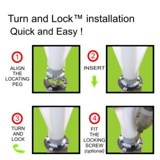
| Key Features | Manual Driving Tool for the GS001 Turn and Lock™ Ground Spike. The driverr is designed to slide into the top of the GS001 Ground Spike to allow a manual hammer to be used for ground spike installation. JMB's driving tools are designed to protect the top Turn and Lock™ plate while the ground spike is being driven. To Use this driver tool: Simply insert the GS001K driver into the GS001 ground spike until the fin tops are in contact with the base of the slots in the driver tool. Align the markings on the ground spike with the traffic flow, then use a sledge hammer to drive the spike into the ground. Once complete remove the driver from the ground spike. Click the Installation tab for more detailed Installation Information |
||||||||
|---|---|---|---|---|---|---|---|---|---|
| Specifications | Product Specifications Material: Steel Finish: As Machined Mass: 2.35kg Dimensions: ø50mm x 200mm (high) Connection: Turn and Lock™ system |
||||||||
| Installation |
|
||||||||
Manual Driving Tool for the GS001 Turn and Lock™ Ground Spike.
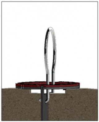
The driverr is designed to slide into the top of the GS001 Ground Spike to allow a manual hammer to be used for ground spike installation. JMB's driving tools are designed to protect the top Turn and Lock™ plate while the ground spike is being driven.
To Use this driver tool:
Simply insert the GS001K driver into the GS001 ground spike until the fin tops are in contact with the base of the slots in the driver tool.
Align the markings on the ground spike with the traffic flow, then use a sledge hammer to drive the spike into the ground.
Once complete remove the driver from the ground spike.
Click the Installation tab for more detailed Installation Information
Product Specifications
Material: Steel
Finish: As Machined
Mass: 2.35kg
Dimensions: ø50mm x 200mm (high)
Connection: Turn and Lock™ system
|
Installation Instructions for Turn and Lock Ground Spikes ;are also available from the Technical/ Information Page |
|
|
Click on image |
Technical Instruction: Installation Dwg - Ground Spike
|
|
Click on image |
Installation Instruction: Installation Guide - Ground Spike |
|
Click on image
|
Removal Instruction: Removal Instruction - Ground Spike |